My first steps in CNC-milling with solid wood
Here is a bit of reports from my experience in CNC-milling with solid wood. I'll explain the incentives that lead me to this project and I'll give some technical detail about the whole process, from design and problem-solving, to the actual workflow explaining what software and hardware came into play and how I used and parameterized them.
Global Workflow
- Ideas, sketches, and solving CNC-milling specific problems with pen and paper
- modeling with FreeCADand exporting upper and/or lower faces (depending on which is to be milled) in 2D DXF (Autodesk)
- Creating the GCode that defines the path taken by the router to mill the shapes we have designed with ArtCAM
- Preparing the machine, opening and previewing the generated path, and attach the piece to be milled e the work area
- Mill the piece, detach it and cut the remaining bits on the milled piece
Design and sketches
The goal: produce a stool made of solid wood pieces which joints are made with a CNC miller instead of traditionnal carpentry tools. We also want to bend a wood board in order to get a more confortable sitting part.
Modeling with FreeCAD
I decided to use FreeCAD since it's libre and free software, natively available on Linux, and of good reputation. The parametric approach is also of great value here since:
- I will often have to modify the model according to the dimensions of the wood I manage to get sourced,
- I want to be able to adapt the dimensions of the final product to fit specific needs, e.g shrinking a library to fit it between a door and another piece of furniture.
WorkBenches used
The stool is made of several parts that are all in the same project file. This approach is more complicated since the placement of parts with full history is more cumbersome than when assembling separated parts (each made in a separate file) into a dedicated project. The advantage though is that its possible to base some parts on other parts sketches (clone) thus making it simpler to propagate the changes to other dependent parts. - PartDesign to make all the features of each part - Part fusion when relevant to assemble subparts into one part - than Draft move/rotate the base sketch of each part to place the parts - When relevant (for male/female type of joints e.g), cloning a sketch used for a "pocket" of one part to make the male-corresponding "pad" of another part; - when relevant, Part-mirroring or Draft-fusion to produce some parts
CNC-milling related problems
One has to take into account from the modeling step the cylindrical shape of the cutting bit and the fact that it is always cutting along an orthogonal axis with respect to the plan of the piece. Therefore the following features have to be adjusted to be feasible with a CNC router (at least the classical 3 axis we are using here).
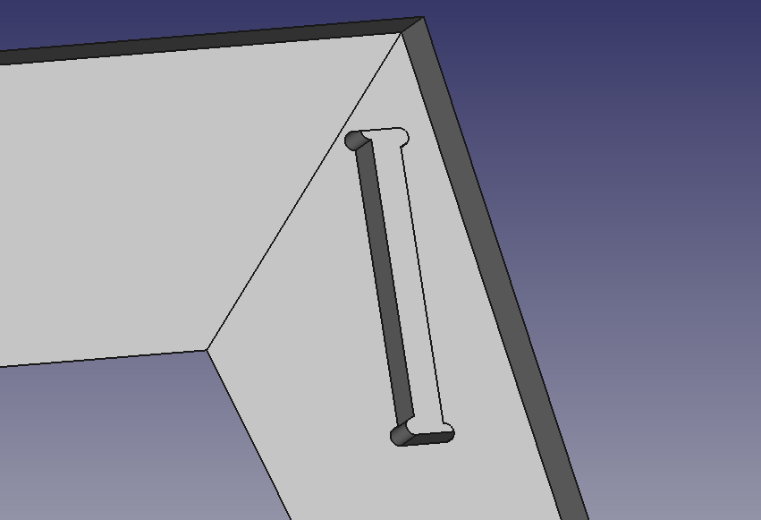
- Inner sharp angles
- Inner sharp angles cannot be realized due to the nature of the cutting bits. Therefore, in order to achieve the same functionality as sharp angles --for instance when doing a tenon-mortise type of joint--, one has to make an "ear-like" shape around the sharp angles, like in the picture aside.
- Minimum radius of some curves
- For the same reason, one has to be carefull even for curved shapes that the radius of the arcs or ellipses are not inferior to that of the cutting bit we'll have at our disposal.
Exporting
- In "Preferences" menu, export settings, ticked the option so that 2D DXF exports made from current view projections
- then select each part and export to DXF
Generating router paths with CAM software
(hope to find a more free/libre approach)
Using ArtCAM
Due to licence limitations, had to use 2 versions of ArtCAM to produce the 2 types of works I need:
- voidings for milling mortises, shoulders with ArtCAM 2015 (nonFree)
- profiling for cutting along the outer shapes of the parts with ArtCAM2017 (free)
Parameters
At this step of the workflow, one has to already know which milling bit to use, which material, and how the piece will be placed on the machine.
Here are the parameters I used:
- Tool used:
- type: double helicoidal
- diameter: 6mm
- Z pass: 6mm (how much down it goes at each pass)
- Tool nominal Rotation speed: ? rpm
- feed speed : ? mm/mn
- mandrin rotation speed: ?
- Bridges (bits of material uncut so that the piece stays in place):
- length: 5mm
- height: 3-5 mm
- type : 3D (makes it like a little "mountain")
- number: 4 to 6
The machine used
FDA Automation <>